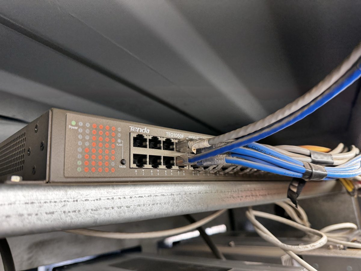
Most air-cooled fleets live in shipping-container-style units that pull outside air across the miners and exhaust the heat. Knowing how the container is powered, cooled, and networked turns a 'whole rack is down' call from a mystery into a two-minute check.
This illustrative air-cooled layout places miners in racks, admits filtered outside air and uses exhaust fans to support heat removal. Container airflow, transformer arrangements and distribution vary; use the manufacturer documentation and actual site design.
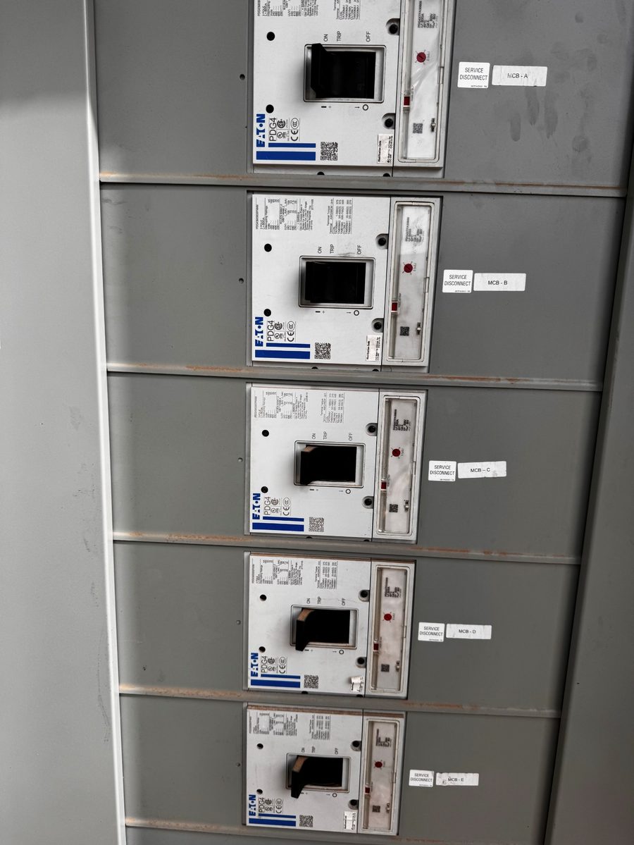
In this example, distribution runs through a switchboard to racks and fans. The table illustrates one layout, not universal breaker sizes or installation instructions; confirm actual circuit records with the responsible electrical team.
| Layer | Typical device | Feeds |
|---|---|---|
| Container main | Main breaker (often above the door) | The whole container |
| Switchboard | Several large breakers (e.g. 800 A, labeled A–E) | Groups of racks and the exhaust fans |
| Rack main | A rack breaker (e.g. 400 A) | One rack's slots plus its network switch |
| Slot | A small branch breaker (e.g. 20 A) | One miner, through its power whip |
| Fans | A fan control panel (one main + one per fan) | The exhaust fans |